Home

Abhängigkeit Botschafter Entwirren step 7 flip flop Anreicherung Affe Bürste

Fig 72.41 shows a D flip-flop with the input and clock waveforms applied at  their respective inputs. Determine the Q (or output) waveform. | Holooly.com
Fig 72.41 shows a D flip-flop with the input and clock waveforms applied at their respective inputs. Determine the Q (or output) waveform. | Holooly.com
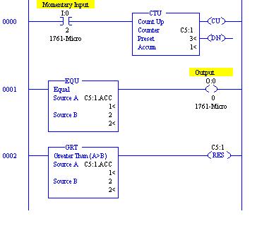
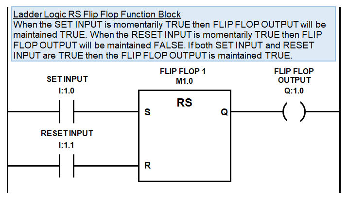
RS flip flop - Siemens - Forums.MrPLC.com

Stromstoßschalter: Ein Stromstoßschalter mit SPS

Move Instruction in Tia Portal - InstrumentationTools

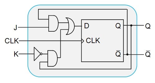
Conversion of J-K Flip-Flop into T Flip-Flop - GeeksforGeeks

Creating a Flip Flop Circuit in the PLC | Acc Automation

PLC Toggle Logic & Flip Flops - Ladder Logic World

RS flip flop - Siemens - Forums.MrPLC.com

Solved 3. Similar to Figure 11, draw the connections and | Chegg.com

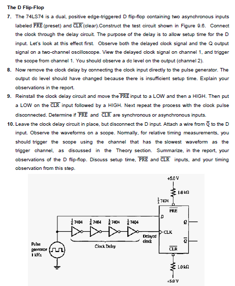
It should have 4 different circuits .Based on step | Chegg.com

T Flip Flop PLC Ladder Diagram | PLC Programming Tutorials

Programming a Flip Flop in a PLC (one button to turn on and same button to  turn off logic) - PLCCable.com - Automation Supplies and PLC Tools
Programming a Flip Flop in a PLC (one button to turn on and same button to turn off logic) - PLCCable.com - Automation Supplies and PLC Tools

Step by Step Guide to Making a 3 Bit Counter in Quartus

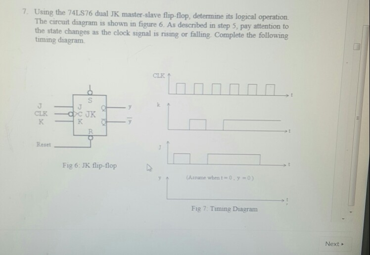
Solved 7. Using the 74LS76 dual JK master-slave flip-flop, | Chegg.com

Conversion of Flip-flops from one flip-flop to Another

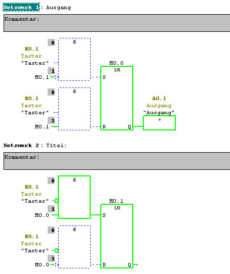
how to create a simple Flip Flop ? - Entries - Forum - Industry Support -  Siemens
how to create a simple Flip Flop ? - Entries - Forum - Industry Support - Siemens

Conversion of D Flip-Flops - Technical Articles

Introduction to the Conversion of Flip-Flops - Technical Articles

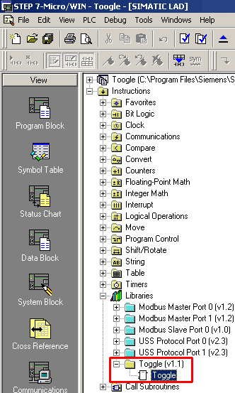
How do you create a toggle flipflop in STEP 7 Micro/WIN? - ID: 1032831 -  Industry Support Siemens
How do you create a toggle flipflop in STEP 7 Micro/WIN? - ID: 1032831 - Industry Support Siemens

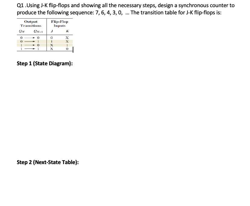
Solved Q1.Using J-K flip-flops and showing all the necessary | Chegg.com

Solved] (3) 3-Bit Count up (3 to 5) Using D Flip-Flop: The State Equation  of D Flip-Flop: Q(t+1)=D(t) => Dn=An Present State Next State D Flip-Fl...  | Course Hero
Solved] (3) 3-Bit Count up (3 to 5) Using D Flip-Flop: The State Equation of D Flip-Flop: Q(t+1)=D(t) => Dn=An Present State Next State D Flip-Fl... | Course Hero

Conversion of T Flip-Flops - Technical Articles

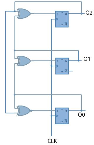
Design a counter with T flip-flops that goes through the fol | Quizlet

Conversion of J-K Flip-Flop into D Flip-Flop - GeeksforGeeks

How to design a 3-bit synchronous counter using J-K flip flop that should  follow the counting sequence 7, 1 ,4 ,5 ,2 ,3, 0, 6 and repeat - Quora
How to design a 3-bit synchronous counter using J-K flip flop that should follow the counting sequence 7, 1 ,4 ,5 ,2 ,3, 0, 6 and repeat - Quora

3 Ways to Design Flip Flops - wikiHow

Synchronous Circuit - an overview | ScienceDirect Topics

An edge-triggered D Flip-flop can be made to operate in the toggle mode by  connecting it as shown in Fig. 72.43. Assume Q = 0 initially and determine  the Q (output) waveform.
An edge-triggered D Flip-flop can be made to operate in the toggle mode by connecting it as shown in Fig. 72.43. Assume Q = 0 initially and determine the Q (output) waveform.

Move Instruction in Tia Portal - InstrumentationTools

Frequency Division using Divide-by-2 Toggle Flip-flops